CNC machining design guide
When designing the parts, you can check our CNC machining design guide. That may help you a lot.
In order to meet the requirements of functions, appearance, and reliability. The design of the part should make the production machinability, efficient, short production cycle, and low cost.
What will the tolerance impact?
> Quality level of raw materials and semi-finished products
> Cost of production equipment
> Cost of testing equipment
> Labor quality and cost
> Rejection rate
The tighter the tolerance, the higher the cost.
With the increase of precision of parts required, more fine processing procedures are required.And production efficiency decreases, the machining cost increases substantially.
The relationship between the cost and tolerance as below chart shown :

Therefore, for mechanical parts, avoid unnecessary tight dimension tolerance for the parts will be better. How to do this? This can be done in two ways:
1. The overall structure of the product:
By designing reasonable gap, simplifying the product assembly relationship, using positioning features, using points or lines and planes instead of planes and planes, etc., to avoid strict tolerance requirements for parts.
2. Parts:
Surfaces with low accuracy & surface quality requirements should not be designed as surfaces with high precision and high roughness requirements. In addition, surfaces that do not need to be processed should not be designed as processed surfaces.
When designing machined parts, you cannot design only from the perspective of a single part, but from the overall perspective of the product. Comprehensively consider the feasibility of the machining of each part, the processing efficiency and the processing cost. By reasonably splitting and combining, the structure of products and parts is simplified. So that the overall product is easy to be machined with high processing quality and low processing cost.
In the original design, the shape of the parts is complex, and the machining takes more time; In the improved design, the shape of the parts is simple, which is beneficial to reduce the processing cost.
1) Try to Avoid curved surface
Try to change the curved surface to a flat surface. The more complex the curved surface, the higher the cost of the machining tool, and the lower the processing efficiency (Because the tool is a ball knife, the cutting area of each movement is very small.).
2) Reduce clamping times
Minimize clamping times, reduce clamping error and reduce auxiliary working hours, improve cutting efficiency, ensure machining accuracy.
— Ensure the position accuracy.
The surfaces with mutual position accuracy requirements are best to be clamped at one time, which helps to ensure the position accuracy between the machined surfaces and reduce the number of clamping times.
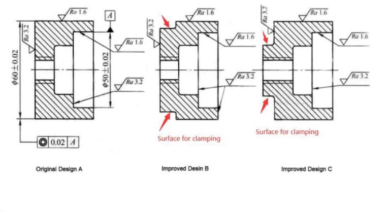
As shown above, the inner and outer circles have requirements of concentrically accuracy. In the original design, the parts need to be clamped to turning process the outer surface and the inner hole separately, which is difficult to ensure the accuracy. In the improved design, the inner and outer surfaces can be machined in one clamping through the boss structure, which can easily meet concentrically accuracy, and the machining cost is also reduced.
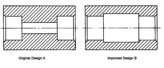
For the parts shown above, the left and right inner holes have requirements for concentric accuracy. In the original design, the parts must be clamped twice to process, and the coaxiality of the two inner circular surfaces is not easily satisfied. While the improved design, the parts can be clamped once for turning, which is beneficial to guarantee concentric accuracy.
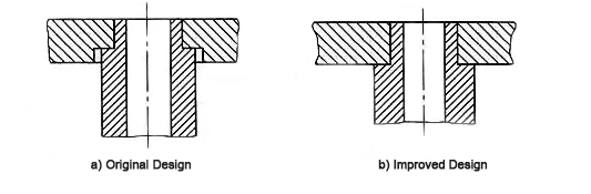
— Change The inclined plane to horizontal plane.
")
When machining the inclined plane of original design, it takes one more clamping. In the optimization design, the inclined plane is changed to the horizontal plane, and several surfaces can be machined at one clamping.
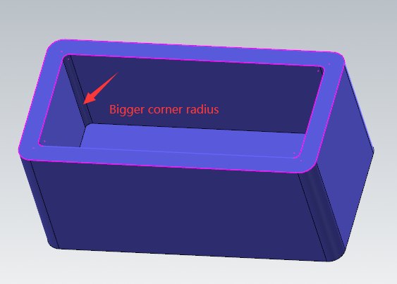
3) Bigger radius for inner corners
When milling a large and deep cavity, generally in order to improve cutting efficiency and tool rigidity, a tool with a larger diameter will be selected. For the inner cavity, the joint on the four sides cannot be a right angle, and all tools will make it necessary to form an R angle. But the smaller the R angle, the smaller the tool is needed to clean the corner, which not only takes more machining time, but also makes the tool’s rigidity worse to get worse surface quality.
4) Improve the rigidity of the structure.
The part’s structure must be rigid enough to avoid deformation from clamping force or cutting force, which decide the machining accuracy and quality also.
— The wall thickness can't be too thin.
")
In the original design, the wall of the part is thin, and it is easy to deform due to the clamping force and cutting force. After the optimized by middle-mounted or thicker wall , the part gets stronger rigidity to avoid deformation.
— Add ribs to improve rigidity.
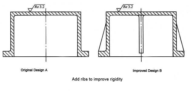
In the original design, the box structure not strong enough. The milling process easily gets it to deform. In the improved design, ribs add to make the structure stronger. So that deeper cutting and bigger feeding rate is available, machining efficiency increase and cost lower.
Use standard parameters as much as possible. The aperture, taper, thread aperture and pitch, gear modulus and pressure angle, arc radius, groove and other parameters of important parts should be used data recommended by relevant standards. In this way, standard knives, clamps, and measuring tools can be used, which no need for special tooling and can reduce the design/manufacturing cost.
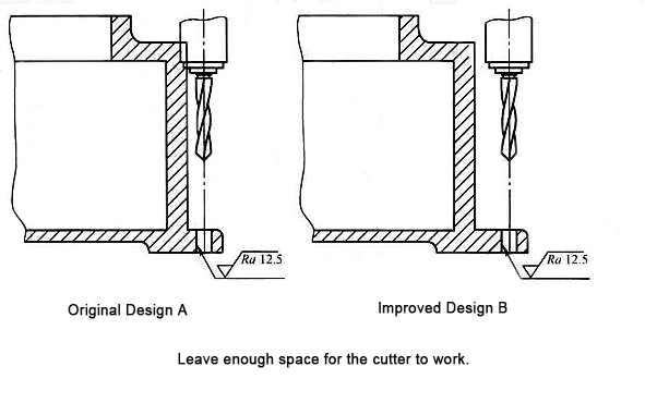
The Structure Of The Mechanical Parts Should Be Convenient For The Tool To Cut In And Out.
As shown in the right sample., in the original design, the hole is too close to the vertical wall of the part, which cause the drill chuck interferes with the vertical wall. Only non-standard extended drill bits can be used, and the tool rigidity is poor. In the optimized design, the distance between the hole and the vertical wall is far enough for the drill to move down. Standard tools to can be used to ensure machining accuracy.
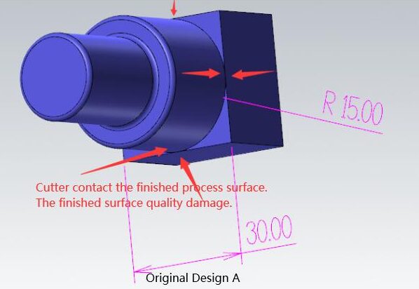
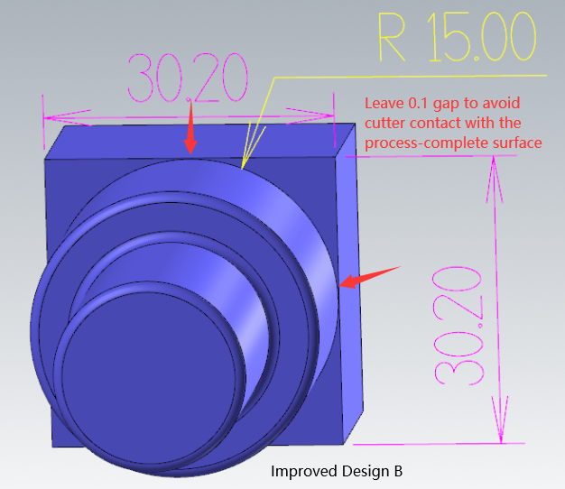
Surfaces with different machining requirements or need different type of process should be clearly separated. This can improve the working conditions of the tool, and can also avoid the tool to contact the finished surface to damage the surface quality.
")
Our precision CNC milling service and surface treatment for the milled components.
")
Check our CNC turning machining service, what kind of products we can produce.
There are many types of machines for machining. Check out to know more about machining.
